


CIRCUITBENDING TIPS
COMMON BENDS
This is a selection of common bends not specific to any machine:
Voltage Drop Crash: If you've ever had the experience of any machine freaking out when the batteries are starting to die then you already know what this bend is all about. This bend is usually installed simply by soldering a low value potentiometer (1K, 470ohm or lower) between the positive power source and the circuitboard itself. In this case you may find that a log curve pot gives you better control that a linear one. When the resistance is increased the voltage input will drop and the machine will act as if the batteries are dying. This does not work on all machines but it especially effective on the Casio SA range of toy keyboards which tend to produce some insane random noises using this method This is the one occasion where a crash is a good thing.
Pitch Knobs: If you have found a body contact point that appears to change the pitch of a machine you will probably need to install a knob to control the pitch. In most cases (on cheap machines) the body contact point will be where the resistor that controls the clock speed of the circuit is mounted. If this resistor is removed and replaced with a potentiometer of appropriate value (470K is a good starting point but use whatever gives you the best range) you will find that you now have a knob to control the pitch. Alternatively you could use a Light Dependant Resistor (LDR) to control the pitch in an optical theramin manner.
A lot of machines will crash if you take the pitch too high or low. If this is the case simply solder a small preset pot (100K is a good starting point) to one of the tags on the main potentiometer and adjust it until the main pot sweeps within a usable range.
This is the most common method of pitch control. It won't work with all machines and don't even bother trying with Yamaha's, but its a good starting point.
Line Output: The most common method of adding a line out to a bent machine is to simply solder a jack socket to the speaker terminals. If the signal level is too high you may have to use this circuit to calm it down a bit:
R1 can be altered for a different output level. Use a higher value for R1 for a lower output at the jack and vice versa
 LED's: There may be several places in a circuit where it is possible to mount LED's. Finding them can be a bit hit and miss and it usually helps if you have a multimeter but on machines with speakers you may find that you can just solder an LED across the speaker terminals to get a light which flashes according to the output of the machine. This may sometimes distort the output so listen carefully to the difference with and without the LED connected.
Body Contacts: If you have found a connection that changes the sound when you touch it (see page 1) you may want to add a body contact control. For this you can use any conductive metal object that you can mount on the casing. All you have to do is wire any body contact point on the circuitboard to your metal object (steel bolts, cupboard knobs and coathanger wires are all good) and then glue or screw the contact to the outside of the case. You will find that the more skin you have in contact with the body contact, the more pronounced the effect. Touching several contacts at once may also produce more extreme effects.
 Patchbays: These tend to come under the heading of 'advanced circuitbending' but are fairly simple to install when you understand the basic techniques. Patchbays are most often used when you have a machine with so many possible bends available that you couldn't possibly install switches for every available option. A good example of this would be the Yamaha VSS toy sampler range. Once you have located the RAM chip on these machines you find that virtually every possible short circuit between the pins on a 16 pin chip produces a good effect. If you wanted every single possible effect available as an individual switch on the front panel you would have to use 106 switches! A better way of bending this machine is to wire every pin of the RAM chip to a socket mounted on the front panel and then use patch cables to make connections between the sockets. This gives you access to every available bend including combination bends.
RECOGNISING COMMON BEND POINTS & AREAS TO AVOID:
RAM & ROM chips:
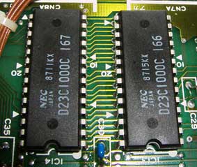
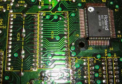
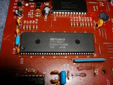
On many machines the main areas to test for potential bend points will be the pins of ROM chips where preset sounds are stored (Drum machines, some synths) and RAM chips where sampled sounds are stored (sampling keyboards). Both RAM and ROM chips can usually be recognized by the fact there will be 2 or three identical chips side by side, which have the pins of one chip connected to the same pins of the next chip with circuitboard traces as if the chips are stacked up (see ROM.1 below). In these cases it is usually only necessary to test one chip as each one will react the same. Chips stacked up in this way will also usually have a hardcore looking CPU chip very close by as can be seen on ROM.3 below.
 |
 |
 |
ROM.1 |
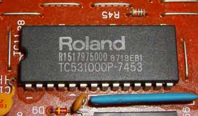
ROM.2 |
ROM.3 |
In most bendable machines both the RAM and the ROM chips will have between 28 and 32 pins. If they are not stacked up then they commonly have the name of the machines maker printed on them as shown on the Roland sound ROM chip in ROM.2 above 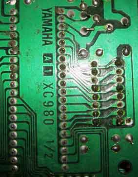
Bendable RAM chips are usually mounted on the circuitboard using the 'stacked' method shown above but it is also fairly common on sampling keyboards that only have one sampled voice, to find a small RAM chip directly next to a huge CPU chip with all the pins of the RAM linked directly to the larger chip. This is shown on the image of the main CPU and RAM chip from a Yamaha VSS-30 sampling keyboard to the right. You may find it helpful to do a google search on the serial number of the chip you think is a RAM chip to see if you can find a data-sheet with some more information.
CPU's and OS chips:
That big Yamaha CPU chip may look obscenely tempting to the inexperienced circuit bender but if you don't have much experience with these things our advice is to leave it well alone. You may find a couple of good bends on one of these chips but more than likely you will end up wiping a machines memory or possibly corrupting it's keyboard scanning and operating system. If you insist on testing one of these chips for bends you should first try to trace back the circuitboard traces to see where they end up. As you can see on the Yamaha photo tracing 16 of the pins back leads to the chip on its right which happens to be the RAM chip, so you know you are safe with those pins. In that case you may as well just test the RAM chip pins for bends and avoid accidentally frying the RAM and / or the CPU by connecting them to random chip pins. If in doubt about any chip, FIND THE DATASHEET and check it out before probing blindly
 |
 |
CPU from a Roland TR-505 |
OS chip from a KORG DDD-5 |
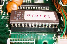
The other type of chip you really don't want to be messing with is a machines Operating System chip, unless of course you never want it to work again, in which case go ahead :) Corrupting the operating system is usually the end of any machine as its very unlikely you are going to be able to replace it. OS chips can often be recognized by the fact that they are the only chips on the board that are mounted in IC holders as shown by the Korg DDD-5 photo above. Presumably many manufacturers changed and developed the OS for their machines over their production lifetime and so the OS chip had to be easily replaceable by the user in case they needed to update it. OS chips also commonly have stickers with the version number printed on them and / or the product manufacturers name.
ADDING PITCH CONTROLS TO MACHINES WITHOUT A PITCH RESISTOR:
If you want to add a pitch control to a more complex machine that doesn't have a simple resistor to control the pitch, then it is most likely that you will be needing a controllable method of replacing the high frequency oscillator that provides the system clock.
This can be done in various ways, but the most stable and quickest method is using an LTC1799 precision oscillator chip built on a small stripboard circuit to replace the original clock signal with a variable control.
Details of how to build a stripboard based LTC1799 oscillator can be found in our free DIY guide HERE, along with our basic installation tutorial HERE.
We also sell LTC1799 chips pre-soldered to a handy DIP-6 adapter board or as a complete reclocking module in our shop HERE.
DISCLAIMER: Circuitbenders can take no responsibility for anything whatsoever.
No, really, Circuitbenders can't accept any responsibility for any damage, loss or injury caused by the use of the information supplied on these 'tips' pages. All circuitbending is carried out at your own risk. In other words, if you die it's not our problem