
FITTING A LTC1799 PITCH CONTROL
MODULE TO A ROLAND TR505
This tutorial shows you how to quickly and easily fit one of our LTC1799 precision oscillator modules to a Roland TR505 drum machine. This will provide you with a wide ranging control that will change the sample playback speed, and therefore the pitch of all the sounds simultaneously.
It will also work with other LTC1799 modules, or a home made LTC1799 oscillator built on stripboard, but we have used one of our modules here for the sake of simplicity. This tutorial uses an older version of the module, but the pin out and installation of the new version is identical.
Firstly you need to open up the TR505 and take out the main PCB. To do this you need to pull off the volume and tempo knobs, and then remove the three screws in the back of the machine. This should allow you to separate the two halves. Disconnect the wiring looms on the left hand side from the front panel by simply pulling the connector blocks out of the switching board.
On the top left of the main PCB you'll find the battery compartment connector. Disconnect it, and then remove the two screws on the left and the right that hold the main PCB in place.
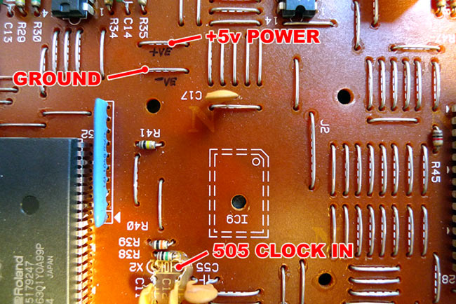
Now you need to find the blue component shown in the image below. This is the ceramic resonator that supplies the digital clock to set the speed of the sample playback, it will be labelled as component X2.
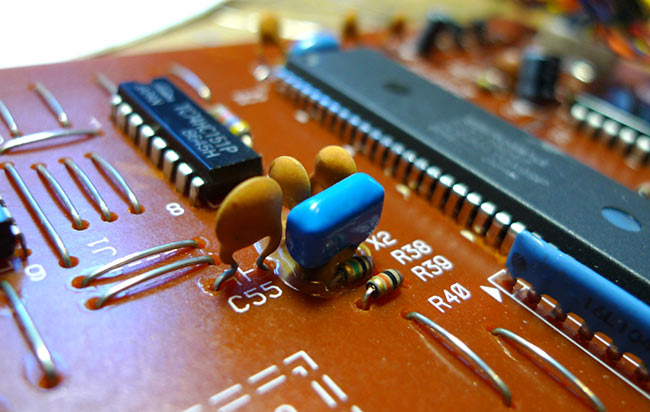
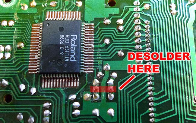
You need to remove this component by desoldering it from the board on the other side, and then pulling it out. You may find this a little more difficult than you anticipated, as for some reason Roland chose to glue this component into place. Luckily the glue has probably perished by now so it shouldn't be too difficult to get it out.
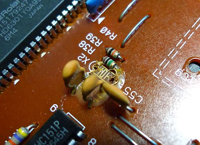
Once you've got it out, it should look like the image below.
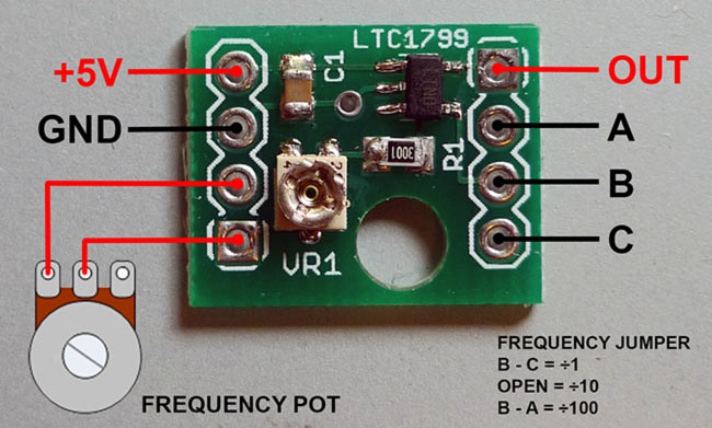
Before going any further, find your LTC1799 module and make yourself familiar with the inputs and outputs using the diagram below. You will need to solder a short jumper wire between holes B and C, to set the module to the correct frequency range. This can be done using any bit of wire, but a cut off component leg is probably the easiest.
This is an earlier version of the LTC1799 PCB module than the one you will probably have, but the pinout is the same.
Now you need to find the areas shown on the image below. The two wire jumpers labelled '+5V POWER' and 'GROUND' are where you need to connect the power for the LTC1799 module. Make absolutely sure that you have the correct jumpers here. If you get it wrong it'll either not work, or the LTC1799 module will go up in smoke! Soldering to the jumpers will probably be easier if you try to flow some solder onto the jumper itself, before attempting to solder a wire to it.
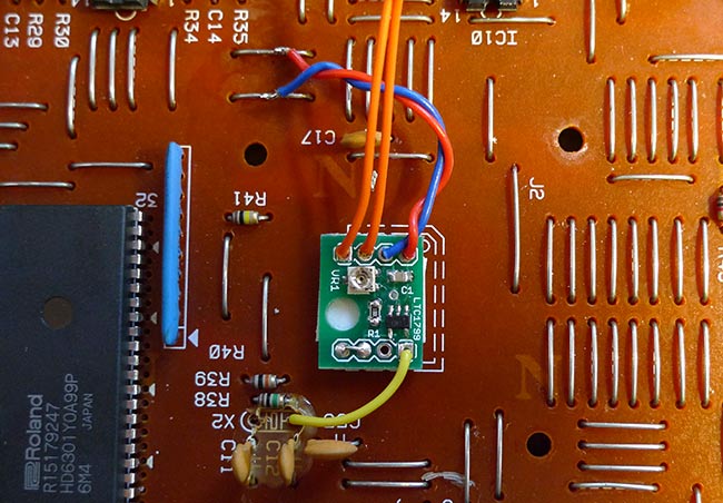
Connect the LTC1799 module as shown below. The clock output from the module should be wired to the right hand hole from where you removed the ceramic resonator. In this image you can see the wire jumper to set the LTC1799 frequency range has been soldered into place, and the power has been wired to the correct wire jumpers on the 505 board. You can mount the module using a bit of that double sided sticky foam you can buy in any stationers. You could probably glue it in place at a push, but we wouldn't recommend relying on the wiring to hold it in place, especially not with all those other wire jumpers nearby.
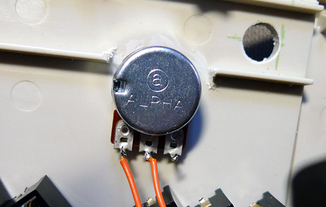
The two orange wires run to the potentiometer that controls the pitch. We usually use a 1 MEG pot with a anti-log response curve, known as a C1M pot. Don't use a linear pot or you'll find all the top end response only happens in about 10 degrees of the pots rotation. You can use a normal log response pot and the response curve will work ok, as long as you wire it so it'll respond in the opposite direction to what you'd expect i.e. turning it anti-clockwise raises the pitch.
The image below shows how you wire an anti-log pot. Use the middle and right hand pin with a normal log pot.
Once you've done this you should turn the TR505 on, play a pattern and check the the knob actually changes the pitch. If its all working well, you now need to set the highest pitch without the machine crashing. To do this you need to set the pitch knob at its highest setting while the machine is playing, and then take a small screwdriver and adjust the tiny trimmer pot on the LTC1799 module so that the pitch is set to its absolute highest setting without the sounds breaking up, or the machine crashing. If the machine crashes or locks up, just turn the pitch down a small amount using the trimmer and restart it. This may take a few attempts, but once you've set it you don't need to mess with it again.
If the machine crashes when you turn the pitch knob up before you've even adjusted the trimmer, then it might already be set to a pitch thats too high. Just turn the trimmer roughly 180 degree
and try again.
The demo below should give you an idea of what kind of pitch range you can expect from this mod.
The LTC1799 module used in this tutorial can be purchased HERE