INSTALLING A LTC1799 OSCILLATOR
LTC1799 reclocking modules or single IC's mounted on a SMD-DIP adapter can be bought from the shop HERE
We have a simple guide to installing a LTC1799 module on a Roland TR505 drum machine HERE, and on old ART effects units such as the Multiverb LT, LTX and Proverb200 HERE
GENERAL INFORMATION:
The components you want to be looking for on the board of your chosen machine are usually a ceramic resonator or a crystal oscillator although occasionally, such as on units like the Casio SK1 where the clock frequency would have to be tuned at the factory, you'll find a rectangular metal component with an adjustment trimmer on the top called a coil. These components provide the original clock signal for the circuit.
 |
 |
 |
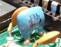
CERAMIC RESONATOR |
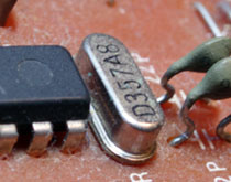
CRYSTAL OSCILLATOR |
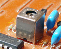
COIL |
On some machines you'll find several of these components, or on machines like the Yamaha VSS200 you'll find one of each to produce a clock signal for three different parts of the circuit.
Each one of these components can come in various different forms. Crystals can be taller or shorter than the one shown but are invariably lozenge shaped metal cans, Ceramic resonators can be different colours and either have two or three legs, but they are usually blue or sometimes brown, and are marked with a value such as 12.0MT, 4.00MG or similar. Coils are usually fairly obvious as they tend to be the biggest components on the board that aren't IC's.
If your machine uses all tiny surface mount (SMD) components then you could be in a world of hurt! SMD boards tend to mostly use crystals which hopefully will still take the form of a metal can. If not then even finding the right component is going to prove difficult. We'd suggest doing a search on google images for 'SMD crystal' or similar to get an idea of what these things look like.
INSTALLATION: (read through the whole guide before starting work)
First identify and remove the original clock source using some solder wick, and / or a solder pump. If you intend to install a switch to select between the original and LTC1799 clock (see below) you will need to get this component out cleanly so take care. It may not actually be necessary to remove the original clock source at all, especially if it is a coil, but it may pay to do so if possible for the sake of stability.
If your machine has several obvious clock sources it is a good idea to leave them in place for the moment and wire up the power for the LTC1799 as below. Then start up the unit with the LTC1799 output connected to each one of the clock source connections in turn and see what effect it has. This may not be very stable but it will help you identify what each clock source is doing, which will then allow to remove the correct one. You might find that as with the Casio RZ1 drum machine, you have one clock for sampled sounds, one clock for the preset sounds and another clock for the overall speed of the system.
If your machine has a coil you may need a slightly different approach. You may get away with just connecting the LTC1799 output to the output of the coil, but on some circuits you can sometimes get better results by tracking the clock signal further into the circuit where it is shaped and amplified by other circuitry, and then cutting a board trace and injecting your LTC1799 clock there. You will most probably need an oscilloscope to track the clock signal though.
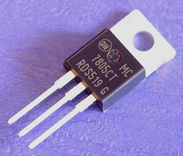
You will now need to find a stable voltage source in the circuit between 2.7v and 5.5v. This is the operating voltage range of the LTC1799. On many machines you will be able to use the output of the voltage regulator that supplies 5v to any logic IC's in the circuit. This will probably be labeled with 7805 in some form and look like the image above, unless you have a surface mount board..
In this case the 5v output will be the RIGHT HAND PIN. Don't get this wrong or you might end up with a dead LTC1799! If in doubt check the datasheet for the regulator. You can trace the 5V line to a point closer to where you want to mount your LTC1799 using a multimeter or just checking the pinout of a nearby chip to find the 5V pin. If you have a meter it pays to make absolutely sure that you are getting 5V where you think you are. It takes seconds to check for voltage but a few days to get a new LTC1799!
Next you need to find a Ground point near where you want to mount your LTC1799. Again, you can find this using the pinout of a nearby chip, but you can also use a continuity tester on a multimeter to find a point connected to the centre pin of the regulator, or even the sleeve / ground connection of any jack sockets on the board.
Make sure the machine is TURNED OFF and connect the +5v power and Ground connections of the LTC1799 board to the appropriate points on the main circuitboard.
Now connect the clock output of your LTC1799 to one of the solder points where you removed the original clock source and turn the machine on. If you have the wrong point then the machine may not start up properly at all, but bear in mind that on many units slowing down the system clock will make the whole thing run slower, so it might take a while to start up. If the machine won't start up and the new pitch knob has no effect, turn the unit off, solder the LTC1799 to the other solder point where you removed the original clock source and try again.
You should now have a pitch control that works to some extent. If you are are using a stripboard design and you find the the machine crashes or locks up when you take the pitch too high, you will need to replace the limiting resistor with something bigger. Alternatively you can just solder another resistor in series with the pot. See the construction guide for details on selecting the correct pot value for the job.
If you are using the PCB module version, you can just adjust the onboard trimmer until the machine no longer crashes or the sound doesn't break up at the highest pitch setting.
Remember that slowing down the clock speed of the whole system will slow down the overall operating speed, so button or drum pad presses may take longer to respond and tempo's will no longer be accurate. Midi functions may also be affected. Many machines have a separate clock for the operating system and for audio playback. If in doubt go for the clock source nearest to the sound ROM or synth chip first.
SWITCHING:
If you're using a machine such as a keyboard that requires some kind of definite tuning at some point, then you may want to wire in a switch so you can select between the original clock source and the LTC1799 clock.
In this case you need to solder the original clock component back in, but leave it disconnected on the side that you have determined that the LTC1799 output should be soldered to. From now on we'll call this the clock input.
This can be achieved by bending the pin out of the way, or you may be able to just cut the circuit traces around where the pin is soldered in. However you do it, the aim is to keep the component as physically close to where it was originally soldered in place as possible, and you also need to be able to solder to the disconnected pin.
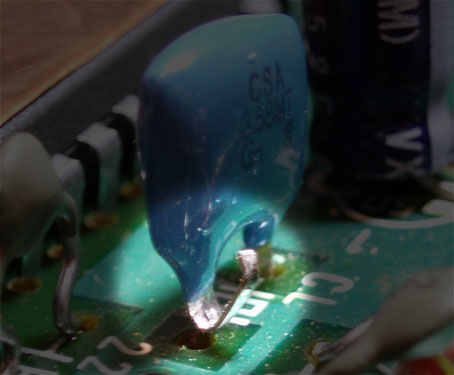
In the example above the ceramic resonator has been removed from the board, one leg has been bent upwards and then the remaining leg was soldered back into place.
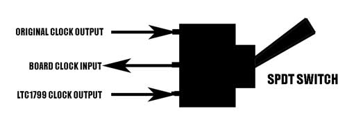
Now you'll need an SPDT switch. Wire the centre pin to the 'clock input' point on the board. Next wire one side to the 'clock output' of the LTC1799, and wire the other side to the disconnected pin of your clock source as shown on the diagram below.
Assuming this guide made some kind of sense and you've wired it up right, you should now be able to switch between the original and the LTC1799 clock. You may find that the machine crashes if you switch between the modes while it is turned on. This is presumably because the switch will probably be of a 'break before make' type, meaning for a millisecond while you switch it over neither clock is connected and the system crashes. Its often the case that you can switch from the original clock source to the the LTC1799 clock while the machine is turned on, but not the other way around. The machine should work perfectly in either mode if you switch it before actually powering the thing up.
If you need any help with this or anything else circuit bending related, feel free to ask on our FORUM and someone should be able to help you out.
Check out our basic guide to building an LTC1799 oscillator on stripboard HERE.
We have a simple guide to installing a LTC1799 module on a Roland TR505 drum machine HERE, and on old ART effects units such as the Multiverb LT, LTX and Proverb200 HERE
LTC1799 reclocking modules or single IC's mounted on a SMD-DIP adapter can be bought from the shop HERE