
BUILDING AN LTC1799 OSCILLATOR ON STRIPBOARD.
The next step is very important to get a usable range. On the layout on the previous page you can see a gray connection under IC1 running from pin 2 to pin 4. This sets the oscillators frequency range to a value useful for most circuit bending applications. We usually install this link under the chip using the cutoff leg of the resistor or capacitor as shown below.
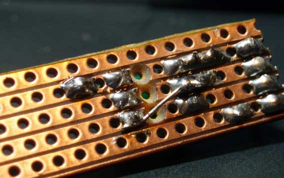
Alternatively you can use two extra wire links on the board to do exactly the same job, as shown by the blue lines on the alternate layout below. Either method works equally well but be careful of shorting anything unwanted together if you go for the underneath method.
The link between pins 2 and 4 of the LTC1799 gives a frequency range suitable for most circuit bending uses, but for slower oscillator speeds you can divide the frequency range by 10 if you leave pin 4 disconnected completely, or by 100 if you connect pin 4 to the +5V input on pin 1
The value of the potentiometer will also depend on the application, but 470K linear (or 500K in the US for some reason) is a good place to start. Certain machines start to produce an unavoidable audible high pitched whine if you run them with a clock that is below a certain frequency, so if you want to avoid this you will have to use a pot that has a value within the usable quiet range.
A good way to discover the best value is to initially use a 1M or 470K pot and turn the pitch up until the whine only just disappears. Then measure the resistance the pot is set too using a multimeter and replace it with the closest pot to that value you can find. To avoid whine completely it would probably be best to use the closest pot of a smaller value but this might not always be the best choice. if you don't mind the whine or it just doesn't happen then just use a pot that gives you the best range. With larger values or certain machines you might find that a pot with a logarithmic rather than linear response curve gives better results, but this is pretty much up to personal preference.
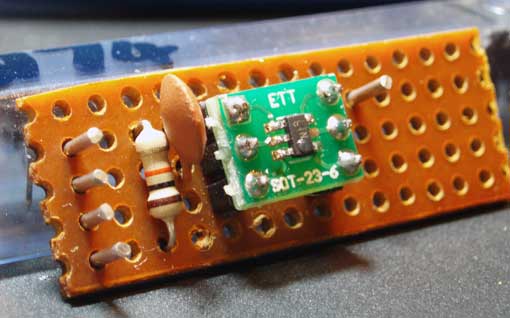
The next step is to install the board pins if you are using them. Its not strictly necessary as its entirely possible to just strip the end of your wires, stick them through the board holes in the right place and solder them in, but board pins do tend to give a more durable connection and its a lot easier to desolder and resolder connections if you need to for whatever reason. The pins should be soldered in the positions shown on the layout and image above.
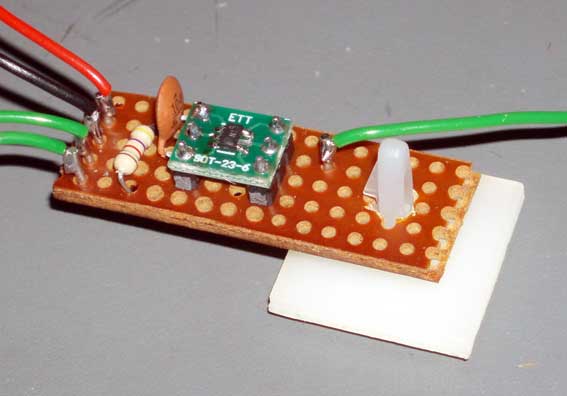
Its probably now a good idea to think about how you are going to actually mount the new oscillator inside the machine in question. If your board is the same size as the one recommended you will have a blank area to the right which you can now use to drill a mounting hole for whatever method you want to use. In this example we have chosen to use a mounting post that clips through the board and has a adhesive pad on its base that sticks it to just about any surface. If you use a metal mounting post take care to stop it from shorting the board strips, and by extension the pins on the LTC1799 together.
Congratulations, you've built yourself an LTC1799 timing oscillator! If you have an oscilloscope now would be a good time to hook it up to the clock output, power up the oscillator and check that the output changes frequency when you turn the knob. Alternatively you may be able to hear the output as an audio signal if if you connect an amp to the output, but this will depend on what frequency ranges your oscillator is set to cover. The LTC1799 can reproduce frquencies from 1KHz to 33MHz but you won't be able to hear anything over 20KHz, and probably not even that high if you've been spending time making enough noise to be wanting to build this ;-)
We also have a general INSTALLATION GUIDE that covers the basics of installing a stripboard based LTC1799 on many machines.