
RECLOCKING AN ART
MULTIVERB LT / LTX / PROVERB 200 & OTHERS
On this page we're going to detail the installation of a LTC1799 oscillator module to control the system clock of an ART Multiverb LT, LTX or Proverb 200 effects unit.
There are probably several other ART units of the same era that can be modded in exactly the same way. These three use more or less the same motherboard so we would assume that there are others such as the original Proverb or the other cheaper Multiverbs that are the same.
The same reclocking concept can be used on many other effects units by other manufacturers.
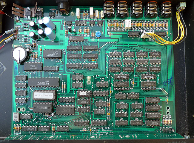
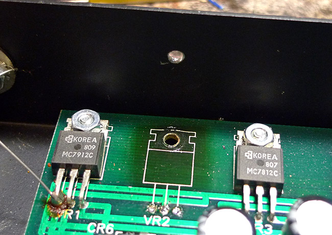
Above you can see the main board for the Proverb 200. There are minor difference between the different units, but the layout is more or less the same.
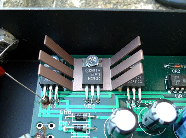
Before you install the reclocking mod, we would advise you fix the inexcusably poor heat dissipation for the 5v voltage regulator. The 5v regulator gets incredibly hot on these units, and will only get hotter when you've installed the reclocking mod and it pulls more current at faster clock speeds. On very early versions of these units you will find no heatsink at all on the 5v regulator. Unsurprisingly these units are usually already completely dead, or have large burn marks on the top left of the board. Later on ART appeared to realise there was a problem and started using the vaned heatsink shown in the image below, but even this was hopelessly inadequate and appeared to be designed to only stop the regulator from burning out until after the warranty had expired!
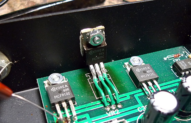
Eventually ART started using the heatsink shown below, which thermally couples all three regulators to the casing via a big chunk of aluminium. This finally did the job properly and we've never seen overheating problems with units with this design.
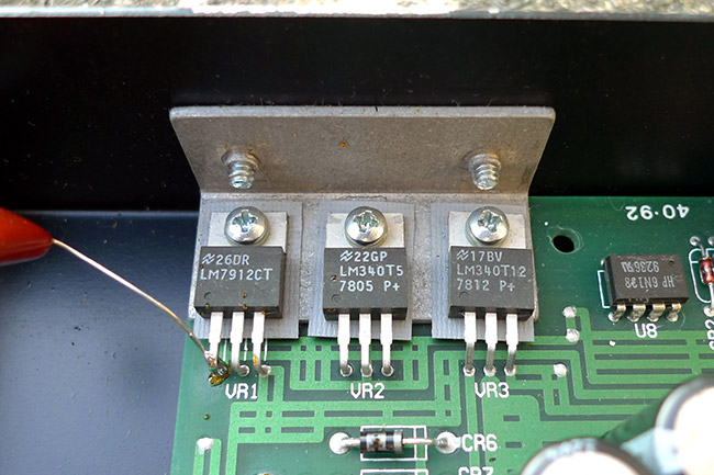
If you open up your unit and find this heatsink then you are probably ok and can skip this stage, but if you find the vaned heatsink, or no heatsink at all on the middle 5v regulator, then you will need to remove it from the board and mount it on the casing so it can use the entire metal case to dissipate heat.
To do this you'll have to unscrew the nut holding the 5v heatsink in place, and then bend it upwards to pull out the heatsink from below it, if there is one. Make sure you remove the screw from under the board as you don't want that knocking around loose inside the case and you can reuse it to reattach the regulator later on.
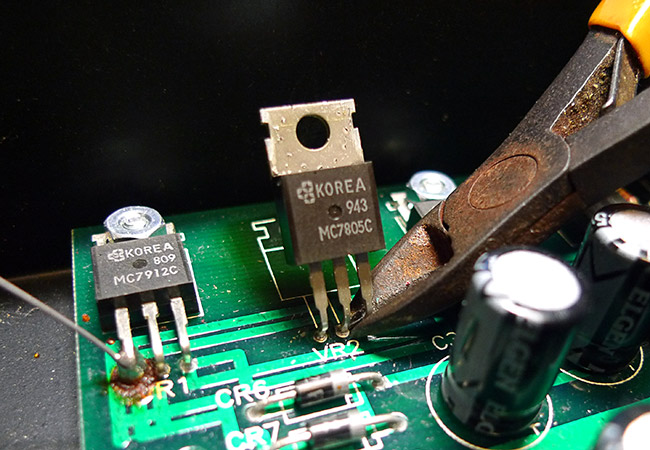
You should then remove the regulator either by cutting it off the board, or melting the solder of each leg one by one and slowly levering it out. Its probably a lot easier to just cut it off the board, but bear in mind you will be reusing this part, so try to make it as neat as possible.
Once you've got the regulator out you should drill a 3mm hole in the rear of the case, approximately 1cm down from the top, as shown below.
This image shows the scorch marks left on the board even with the vaned regulator in place!
Then simply bolt the regulator to the casing via the hole using the nut and bolt you removed earlier, and solder the pins to the vacant terminals you removed them from. Ideally we'd advise using some kind of heatsink compound between the regulator and the case, as used on computer CPU's
RECLOCKING
For this you'll need a LTC1799 oscillator module. These are available in our SHOP. You will also need a C100K or C500K potentiometer. C100K will give you a decent range of usable effects with accurate frequency control, but a C500K will also give you a much lower range of clock speeds where the effects become completely unrecognisable, albeit with less precise control over the 'usable' range. We usually go for a C500K pot.
Pots with an A (log) response can be used at a push if you can't get one with a C (anti log) response curve. A logarithmic 'A' pot will work the same, but it'll operate in the reverse direction.
Find the area on the bottom left of the circuitboard that looks like the image below:
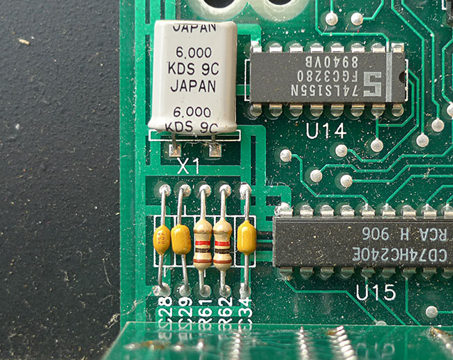
Its may not look exactly like that on your unit, but the layout should be the same.
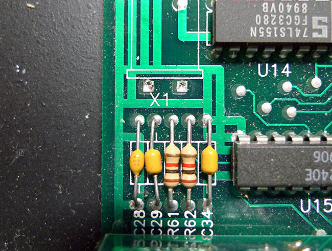
The can shaped component labelled X1 is the system timing crystal. This should be removed from the board either by cutting it off, or melting the solder on each leg and pulling the pins out of the board. You should be left with something that looks like the image below.
Once you've got the crystal out you can prepare your LTC1799 module. Make sure you set the timer range correctly by shorting the 'frequency jumper' terminals B and C as described on the LTC PCB page. This is VERY important.
The output of the LTC1799 board should be soldered to the left solder terminal of X1. The positive +5v power for the board should be soldered to the BOTTOM of C34 and the ground to the TOP. Make absolutely sure you have these the right way round, or the LTC1799 board might go up in smoke.
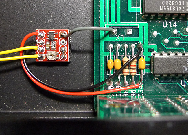
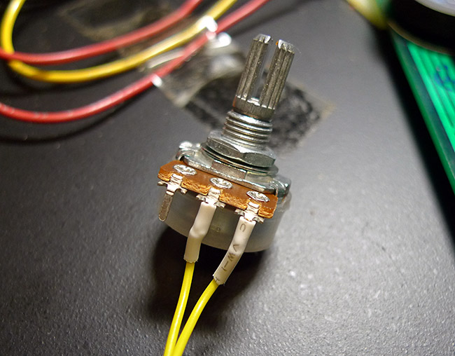
The frequency pot connections (yellow wires in the image above) should be soldered to the pot as shown below. This results in the clock speed being higher in a clockwise direction.
If you have a logarithmic 'A' response pot use the middle and left pins. The clock speed will be higher in an anticlockwise direction, but at least the response curve will be more usable than using a linear pot.
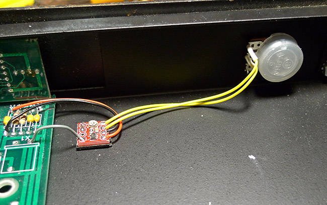
Drill a hole in the front of the case and mount the pot wherever you want it.
All you need to do now is to set the maximum clock speed trimmer on the LTC1799 board.
To do this you should set the pot around halfway up, plug in your audio inputs and output, then turn the unit on. If all has gone to plan you'll probably be hearing some grainy effects obviously processed fairly slowly
at this point.
Turn the clock speed up using the pot either until it gets to maximum, or until the effects break up and distort. If you've got to maximum without the effect dropping out or distorting then you can then use the trimmer on the LTC1799 board to slowly raise the clock speed until the effects break up, and then carefully lower it again to below this point. This has set the maximum clock speed to just under the crash point.
If the effects break up before the pot is set to maximum, use the trimmer to lower the clock speed until you can get the pot to maximum without the effect breaking up, and then use the same technique as described to set the maximum clock speed
You should now have a reclocked ART effects unit!
Demos can be found on the main ART effects unit archive page that can be found HERE.