
ROLAND R5 & R8 POWER SUPPLY BYPASS
The power supplies for the Roland R5 & R8 drum machines are a classic piece of absolute Roland bastardry! Not only are they supposedly specified at +10v/0/-10v (which the really don't need to be) but they also use a proprietary Roland power connector that was never used in any other machine. Essentially this means that if you lose the power supply or it dies for some reason, you're pretty much stuck with either some kind of DIY workaround or paying Roland a ridiculous amount of money for a replacement.
In the past we have got around this issue by building a DIY external power supply and bypassing the annoying power connector using a new 3 pin DIN plug installed on the side of the machine. In emergency circumstances we've even gone so far as to press a PC power supply into service to use its +/-12v power rails!
Building your own mains power supply does involve a fair amount of work and some potentially
dangerous voltages, so we decided to sort this problem out once and for all using a switched mode dual rail power supply PCB that can generate both positive and negative power rails from a single DC input. This allows you to use a standard external power supply in place of the Roland original.
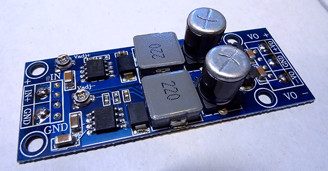
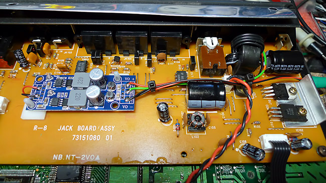
These PCB's are readily available from China via ebay or Aliexpress. The one we used as shown above is possibly overkill for this job as it can deliver far more current than the R8 or R5 will ever draw, and it has output voltage adjustment trimmers which aren't really necessary. We originally chose this one as it will output the Roland specified +/-10v from a 12v DC input, but having looked at the internal power arrangements it appears that the R5 and R8 will be quite happy running on +/-9v output or even +/-12v at a push (although the drum machines internal heatsinks get a little warm on 12v), so as long as the board you use can output something in that range you should be ok. If you're using an adjustable output board, make sure you adjust it to the correct output voltage before installation.
It appears that like many manufacturers, Roland have specified an unusual PSU voltage just so people think they need to buy an official PSU, although they had that pretty much already covered with the unique connector!
The R5 and R8 have a normal current draw of approximately 220mA on the positive rail and 100mA on the negative. This is within the abilities of virtually every one of these dual power PCB's that we've seen, but its probably a good idea to check the specs of your specific board if you're using something different,
Your external DC power supply should probably be rated at a minimum of 500ma or more. For this particular dual power PCB we are using a 12v external power supply
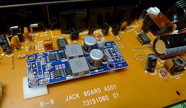
First mount the PCB inside the machine. The R8 has plenty of space and this dual power PCB has mounting holes that can be used with adhesive PCB pillars. The R5 has a little less room, and other power PCB's don't have mounting holes, but it shouldn't be too difficult to fix it securely in place with some double sided adhesive foam or similar.
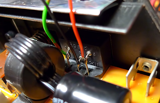
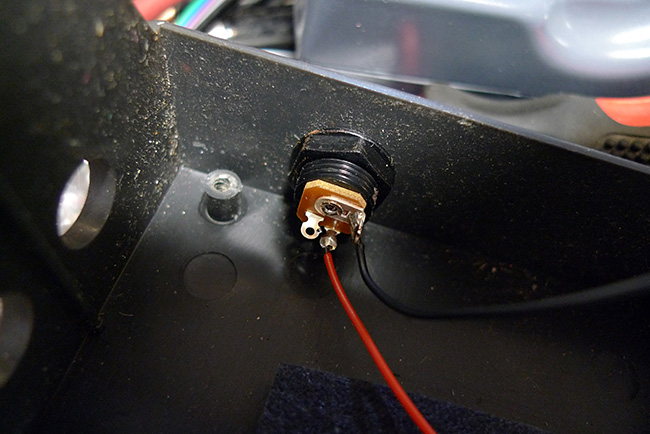
Now you need to solder wires to the three pins on the back of the power socket on the R8, or the labelled +10v/GND/-10v pads where the power socket solders in on the R5. On the image above the green wire is 0v or ground, the red wire is positive voltage and the black wire is negative voltage. The wires need to be long enough to reach your dual power PCB.
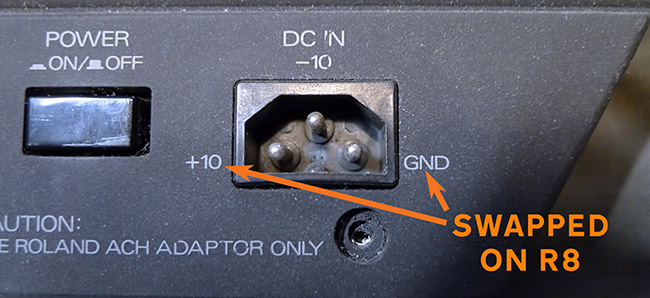
IMPORTANT: THE POWER SOCKET ON THE R8 IS LABELLED INCORRECTLY!
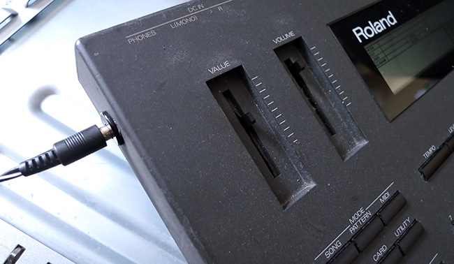
On the back panel of the R8 mkI as shown above, the power socket is labelled incorrectly and has the GND and +10 connections swapped over. From images we've seen on the net it looks like Roland fixed this on the R8 mkII, but we're not 100% sure. If its labelled like the one above, then its wrong. This has probably been the cause of endless messed up attempts to get an R8 running without the official PSU. Use the wiring image above, NOT what it says on the R8 socket.
The R5 socket is labelled correctly, and it also has the correct connection points labelled on the main board just behind the power socket.
Now mount a DC power socket somewhere on the casing and solder wires to it that will reach the dual power PCB. We've wired this one for Roland polarity (centre negative) but is doesn't matter which way round you do it as long as its the same polarity as your external power supply.
Solder the two wires from the DC socket to the voltage inputs on your dual power PCB, and the three wires from the original power socket to the correct power PCB outputs, and you should now have a Roland R5 or R8 that will run perfectly on a standard external DC power supply!
What dual power PCB to use and where to get it:
At the time of writing this, the dual power PCB we used costs approximately £6-£7 and can be found easily on ebay or Aliexpress. Just do a search for "30w DC buck step down dual power supply" or various combinations of those words. You can find one on Aliexpress HERE or on ebay HERE, but obviously those links won't last forever.
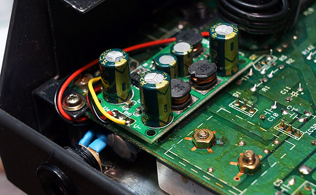
We have also used the +/-10v version of the 'Eletechsup DD1912PA' on as R5 as shown below as there is less room to play with than on the R8. These are available very cheaply all over Aliexpress.
This should also work fine on the R8 and is a bit cheaper and smaller than the one above, although the mounting holes are pretty much useless so you'll have to use some kind of double sided foam tape to hold it in place. Be very careful not to short anything to the main board so cut down any protruding solder joints on both the bottom of the power supply board and the drum machines board before sticking the thing down. According to the specs you should probably run it on a minimum input of 12v to get enough output current headroom, although it appears you can go up to 18v maximum if you wanted.
Other options are probably available. Get in CONTACT if you've found something else and you're unsure.